Motor Controls Course
Understanding Motor Controls
Some factors to consider when installing a motor:
1. Horsepower
2. Service Factor
3. Temperature
4. Voltage
5. Full load current
6. Circuit Protection
1. Horsepower
2. Service Factor
3. Temperature
4. Voltage
5. Full load current
6. Circuit Protection
Chapter 1
Symbols and Diagrams
In order to design, read, and interpret motor control circuits effectively, a comprehensive understanding of electrical diagrams is crucial. Various types of electrical diagrams include:
- Functional Flow Block diagram (FFBD)
- One-line diagram or single-line diagram (SLD)
- Circuit diagram
- Connection or wiring diagrams
- Schematic & ladder diagrams
1. Functional Flow Block Diagrams |
2. One Line Diagram |
|
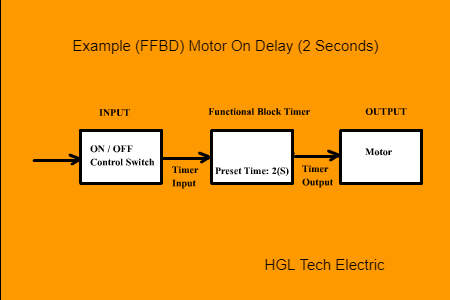
Functional Flow Block Diagrams (FFBDs) are specifically oriented towards illustrating the input and output aspects of a system. These specialized flow charts find application in engineering for system design.
Example: The following FFBD is a representation of an electrical system responsible for controlling a single-phase electrical motor. The design involves utilizing a switch, and the requirement is for the motor to activate after a 2-second delay. |
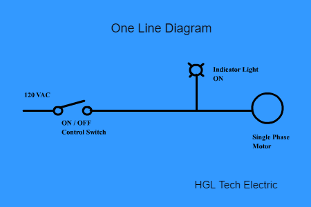
A Line Diagram or Single Line Diagram (SLD) is commonly employed to illustrate three-phase voltage systems, though it can also be applied to represent low voltage control systems. Unlike Block Flow Diagrams, these diagrams utilize symbols instead of geometric shapes to represent electrical components.
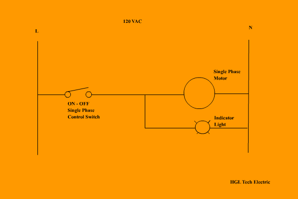
Example: The single-line diagram provided below serves as a representation of an electrical system responsible for controlling a single-phase electrical motor. The system incorporates a switch and an indicator light that signals when the motor is in the ON state. |
|
|
3. Circuit Diagrams |
4. Connection or Wiring Diagrams |
|
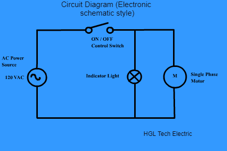
Circuit diagrams are used to display an electrical circuit using either basic images of parts or industry standard symbols. There are two different types of circuit diagrams:
3.1. Pictorial (drawn by using basic images) 3.2. Electronic schematic style (drawn by using industry-standard symbols) Example: The Circuit diagram (Electronic schematic style) below is a representation of an electrical system that controls a single-phase electrical motor by using a switch, and an indicator light that shows when the motor is ON. |
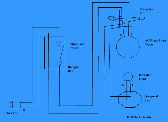
A wiring diagram is a representation of the physical connections and layout of electrical components of the electrical circuit. This type of diagram shows how the wires are interconnected and can also show where fixtures and components may be connected to the electrical circuit. New electricians feel more comfortable reading wiring diagrams.
Example: The wiring diagram below is a representation of an electrical system that controls single-phase by using a switch, and an indicator light that shows when the motor is ON. |
|
|
5. Schematic & Ladder Diagrams
|
Schematic diagrams are the most common electrical diagrams used by electricians, electrical technicians, electrical engineer technologists, and electrical engineers. Note that ladder diagrams are schematics diagrams used to document industrial control logic systems. Ladder diagrams are also very used to program PLCs (Programmable Logic Controllers).
Example: The ladder diagram below is a representation of an electrical system that controls single-phase electrical by using a switch, and an indicator light that shows when the motor is ON. |
|
Ladder Diagram Basics.
|
Summary
1. Electrical diagrams are graphical representations of electrical circuits.
2. The same electrical circuit can be represented in different ways depending on the diagram used. 3. The type of diagram to use depends on the scope, the different disciplines involved in the project, and the regions and standards in different parts of the world. |
Chapter 2
Electrical Symbols
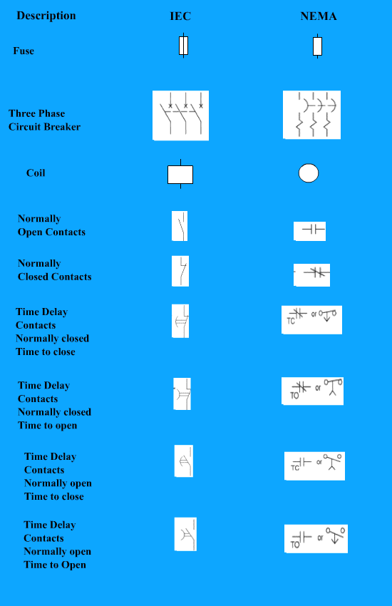
Symbols that represent electrical components and the wires that must be used to design electrical circuits. However, sometimes different manufacturers, companies, or different regions of the world use different symbols to represent electrical components. The most standardized set of symbols in North America is provided by the National Electrical Manufacturer’s Association (NEMA), while in Europe and other regions of the world, the International Electromechanical Commission (IEC) is used.
IEC vs NEMA symbols
Chapter 3 Electrical components most used in Industrial Control SystemsElectrical SwitchesAn electrical switch serves as a component designed to either permit or disrupt the flow of electrons within a circuit. These switches exhibit diverse modes of operation, with some being manually operated (e.g., a light switch or a push button), others being electromechanically operated (e.g., electromechanical relays), and some being electronically operated (e.g., solid-state relays). Furthermore, switches can be equipped with one or multiple sets of contacts, capable of operating simultaneously, sequentially, or alternately.
FusesThis component is an electrical safety device designed to offer over-current protection to an electrical circuit. Its primary element consists of a metal wire or strip that burns or melt when an excess of current passes through it, typically during a short circuit. Fuses play a crucial role in interrupting the current flow during over-current events, effectively serving as sacrificial devices to safeguard the electrical circuit.
|
Push Buttons
A push button serves as a switch mechanism utilized to control the current flow within a circuit. These buttons can be categorized as Normally Closed or Normally Open, with a detailed discussion on these terms to follow later in this course.
Relays
A relay is an electromechanical or electronic switch. This electrical device consists of a set of input terminals for single or multiple control signals, a coil, and a set of contacts. To understand how an electromechanical switch works please refer to the next videos.
